Understanding Pressure Drop in Liquid Cooling: Why Your Data Center Pipes Won't Explode
AI is pushing data centers to the melting point. To keep multi-million-dollar GPU clusters from literally baking themselves, the industry is abandoning air cooling and pumping cold liquid directly to the silicon.
But forcing water through an IT rack packed with 72 dense GPUs raises an obvious question. With that much resistance, aren't the pipes going to explode?
The short answer is no. To understand why, we have to talk about one of the most critical, yet completely invisible battles data center managers fight every single day: Pressure Drop.
The Misconception: Series vs. Parallel Routing
When picturing water flowing through a server rack, many imagine a single garden hose snaking its way from the first GPU all the way down to the 72nd. In fluid dynamics, this is known as connecting in series.
Think of a series connection like a single-lane highway with 72 toll booths. If every drop of water had to push through every single GPU, flow would instantly gridlock.
To visualize the difference:
- Series: Pump → GPU 1 → GPU 2 → GPU 3 → ...
- Parallel: Pump → Manifold → (GPU 1 || GPU 2 || GPU 3)
Every time water passes through a cooling plate, it experiences a "pressure drop" (energy loss, often expressed as head loss, due to friction and turbulence) of about 3.0 pounds per square inch (PSI). If forced through 72 GPUs in a row, those drops would stack up. At over 200 PSI, the system would exceed safe operating limits, leading to leaks, connector failure, or shutdown before the servers even booted.
But data centers do not route water in series. They route it in parallel.
Instead of a single-lane road, imagine a 72-lane mega-highway. The water rushes down a large central manifold and branches off into dozens of separate lanes simultaneously. The water passes through just one toll booth (GPU), then immediately exits onto a wide, clear return pipe.
Because they are parallel, pressure drops do not stack. Whether you have 10 GPUs or 72, the pressure drop across the compute is approximately the drop of a single cold plate (~3.0 PSI), plus minor manifold and distribution losses.
So, Where Does the Rest of the Pressure Go?
If the compute nodes only account for ~3.0 PSI of resistance, why are the heavy-duty coolant pumps working so hard? Welcome to Friction Budgeting.
At the flow rates typical of GPU liquid cooling, coolant flow is fully turbulent (high Reynolds number). In this regime, pressure losses scale approximately with the square of velocity in turbulent flow regimes, making system design highly sensitive to restrictions.
In fluid systems, these effects are categorized as major losses (pipe friction) and minor losses (bends, valves, and fittings), both contributing to total loop resistance. This resistance is commonly modeled using the Darcy–Weisbach equation for pipe friction, along with empirical loss coefficients for fittings.
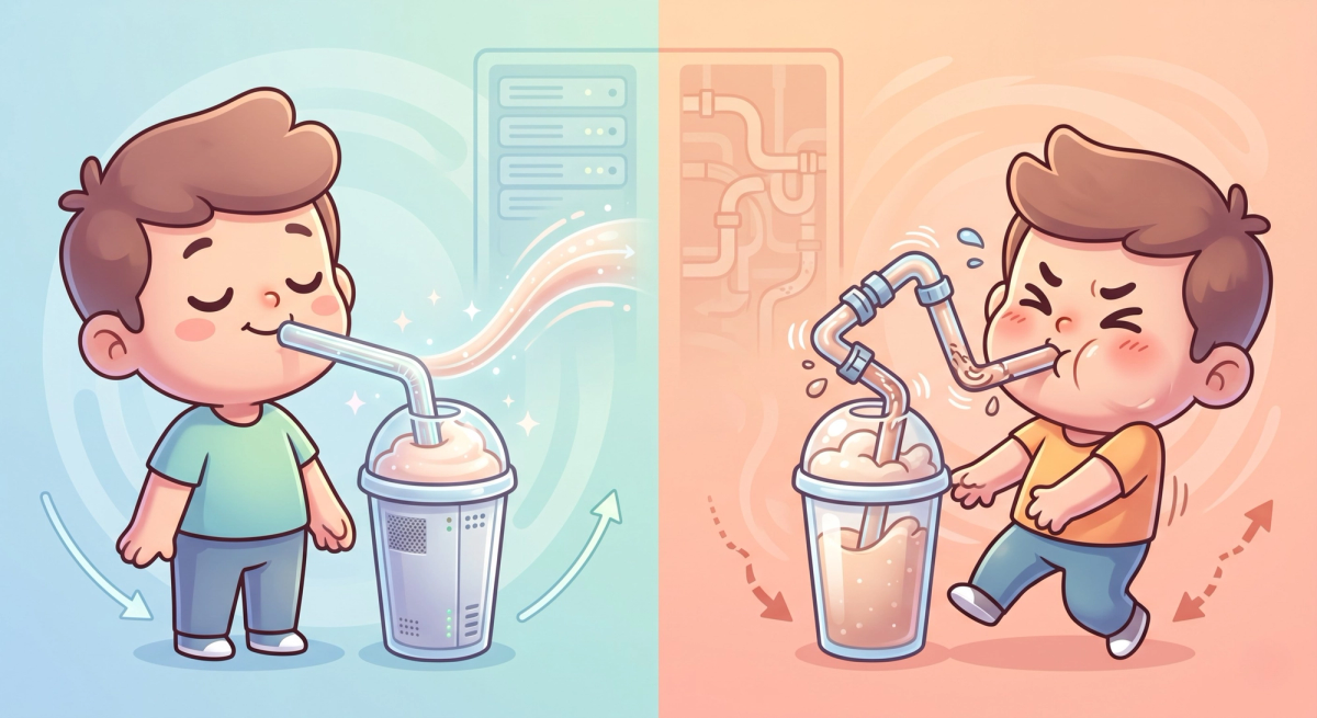
Fluid follows pressure gradients, effectively taking the path of least resistance. Think of drinking a thick milkshake: the liquid itself takes effort to pull up, but if you pinch the straw or bend it, you have to work twice as hard.
In a commercial server rack, total differential pressure does not come from the high-tech GPUs. It comes from the unglamorous "pinched straws" connecting them.
The rest of the budget is lost to:
- Quick-Disconnects (UQDs): The complex safety valves that let technicians unplug servers without spilling. These can account for several PSI, often comparable to or exceeding the cold plate itself.
- Rubber Hoses: The flexible tubes connecting servers to the main pipes. Because the flow is already turbulent, each bend introduces additional minor losses due to flow separation and turbulence.
- Vertical Manifolds: The 8-foot-tall pipes distributing water from the floor. Note that in a closed-loop system, elevation does not contribute to continuous pressure drop; losses are dominated by friction, not elevation.
The Hyperscale Gold Standard
Data center engineers must aggressively account for every single point of friction.
The hyperscale standard for "Differential Pressure" (the total resistance across an entire IT rack) is commonly engineered in the ~5.0 to 15.0 PSI range depending on design targets. Designing within this window is critical not only for efficiency, but also for ensuring uniform flow distribution and proper flow balancing across parallel branches.
If the GPU cold plate consumes 3.0 PSI, engineers only have a strict allowance left to spend on hoses, valves, and turns. If they use cheap connectors or route hoses poorly, they blow the budget. The pumps work overtime, power costs spike, and the system becomes thermally imbalanced.
The Bottom Line
When evaluating a next-generation liquid-cooled facility, look past the processors. The bottleneck is not silicon; it is physics. The operators winning the AI infrastructure race are not the ones fighting the compute. They are the ones mastering the friction.
In high-density AI infrastructure, thermal performance is no longer just a function of silicon—it is a function of fluid dynamics executed with precision.
⚠️RESTRICTED: OPERATOR-GRADE ENGINEERING
You have mastered the basics. Now, let us look at the math. Push the rack pressure to the hyperscale limit (12.0 PSI) to physically breach the containment lock and reveal the Operator Playbook.